
- YS TECH USA Inc blog
- NPI Engineers,
- Re-Spins,
- FEA,
- Thermal Management,
- CFD
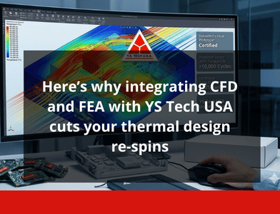
- Here's why integrating CFD and FEA with YS Tech USA cuts your thermal design re-spins
"Do you want to find thermal problems on the bench, or before you cut a tool?"
You already know that late-stage thermal failures cost time, money, and your reputation. When you integrate CFD and FEA early, you stop chasing hot spots, noisy fans, and solder fatigue in hardware. You reduce thermal design re-spins, shorten NPI calendars, and arrive at production with confidence.
This article shows why CFD and FEA integration matters, how it saves you iterations and weeks, and how YS Tech USA's simulation-first approach turns theory into fewer prototypes and faster launches.
How Thermal Design Used to Work
For decades, thermal design was an iterative hardware game. You built a board, stuck a fan on it, and hoped the prototype would pass. When it didn't, you went back to CAD, reworked the heatsink, changed the fan, retooled a bracket, and built another prototype. Each hardware cycle could take weeks and cost tens of thousands of dollars in tooling, lab time, and schedule slippage.
Hidden interactions between airflow, conduction, and mechanical stress were typically discovered only when a prototype failed thermal cycling or acoustic testing. Early methods relied on rules of thumb, vendor datasheets, and simplistic lumped thermal models (approximations that can mask recirculation zones behind heatsinks or thermal gradients across PCB stacks. Structural issues like solder joint fatigue were often overlooked until field returns surfaced.
Why Integrating CFD and FEA Cuts Re-Spins
You can change that pattern by combining CFD and FEA early in NPI. When you merge airflow modeling with structural thermal analysis, you turn unknowns into measurable outputs.
YS Tech USA pilot studies show up to 30% fewer late re-spins and measurable weeks shaved from NPI calendars when teams front-load simulation into their process. You get two complementary views: CFD finds where the air fails to reach, and FEA tells you whether that heat will break mechanical assemblies over time.
Integrating CFD and FEA matters because complex electronics are multi-physics systems. A fan's PQ curve changes when placed inside a ducted enclosure, and that change alters convective coefficients which change temperature distributions on PCBs. Those temperatures produce thermal expansion, which causes stress in mounted components. If you model only one domain, you miss the coupling that causes real failures.
A one degree Celsius improvement can yield roughly 0.5% better system efficiency , and those fractions add up in power-dense designs or high-volume products. Predictive cooling control can cut average power draw substantially, which matters not only for thermal safety but for energy budgets too.
What Integrated Simulation Enables Next
When you adopt a co-simulation mindset, you do more than reduce re-spins. You create a predictable engineering cadence and unlock product features. Expect shorter qualification cycles, fewer field failures, and more predictable warranty costs.
Simulation-first teams can push power density higher, squeeze down acoustics, and prove thermal margins for certifications before a single prototype exists. Your design reviews become less opinion-based and more data-driven.
The Roles of CFD and FEA in Your Thermal Program
What CFD Solves For You
CFD models the fluid side. You get velocity fields, static pressure maps, and convective heat fluxes. Use CFD to find inlet starvation, recirculation pockets behind boards, and whether a fan will operate at the point on its PQ curve where you expect. CFD is the tool for fan selection, ducting decisions, and predicting how enclosure vents and grills change system-level flow.
If you're still working through how to select the right fan or blower for your application, CFD is where that decision gets validated.
What FEA Solves For You
FEA covers conduction and mechanics. You map temperature gradients into stress, fatigue life, and displacement. Use FEA to predict solder joint fatigue from repeated thermal cycles, to ensure heatsink mounting points won't creep under load, and to verify that PCB warpage stays within tolerance during operation.
How They Complement Each Other
CFD provides the convective heat-transfer coefficients and local temperature fields that make FEA inputs accurate. FEA tells you which mechanical changes will alter airflow boundaries or contact conductance, and therefore need to be fed back into CFD. Together, they close the loop that cuts re-spins.
How Integration Actually Reduces Re-Spins
Better Boundary Conditions, Fewer Wrong Assumptions
When you feed CFD results into FEA, you stop guessing at heat-transfer coefficients. You use spatially varying temperatures and fluxes. The result is fewer surprises in thermal cycling and reliability tests.
Faster, Cheaper Iterations
A virtual iteration takes hours or days, not weeks. You can prototype fewer hardware variants. YS Tech USA's experience shows substantial reduction in late re-spins and time saved in NPI when teams adopt simulation-first pilots.
Lower Risk of Latent Failures
FEA-driven fatigue analysis, seeded with CFD thermal cycles, reveals solder and connector vulnerabilities before they become field returns. That reduces warranty exposure and the cost of emergency redesigns.
Acoustic and Energy Optimization
When you model fan PQ curves and motor control behavior inside CFD, you predict noise and power together. That matters for medical equipment, consumer devices, and entertainment lighting where acoustic limits and energy draw are strict design constraints.
How YS Tech USA Embeds CFD and FEA Into Your NPI
A Typical Integrated Workflow
- Requirements and constraints: Define operating temperatures, IP ratings, acoustic targets, and certification needs
- Topology and component selection: Pick fans, blowers, EC motors, and heatsinks that match the load and form factor
- CFD baseline: YS Tech runs conjugate heat transfer simulations with detailed fan models and PCB heater maps
- FEA hand-off: Temperature fields and heat fluxes go into transient structural and fatigue analyses
- Co-simulation and iteration: Designers and engineers iterate until thermal and mechanical targets are met
- Validation and manufacturing: Targeted prototypes validate the model and correlate measurements for production release
Product and Manufacturing Fit
YS Tech offers a range of DC fans, AC fans, EC blowers, and heatsinks that can be tailored for your design. Because the company couples US-based engineering with global manufacturing, you get quick iteration support plus supply chain reliability, which shortens the back-and-forth between simulation and final hardware.
Practical Checklists You Can Apply Now
CFD Checklist
- Run conjugate heat transfer for coupled solid-fluid behavior
- Include fan PQ curves and model rotating machinery appropriately
- Do a mesh sensitivity study with y+ checks near walls and fins
- Use k-omega SST for separated flows
- Include radiation if you have large temperature deltas or outdoor enclosures
- Simulate relevant transient cycles, especially for PWM or intermittent loads
FEA Checklist
- Map CFD temperatures and heat fluxes into the FEA mesh as boundary conditions
- Include thermal contact resistances for adhesives and interfaces
- Run transient thermal cycling and fatigue life estimates for solder and connectors
- Verify bolt preloads and mounting stiffness; check for creep and deformation over time
- Perform modal analysis to catch vibration-sensitive heating pathways
Validation Guidance
- Place thermocouples at simulated hot spots and use thermal imaging to scan the full board
- Measure fan PQ in-situ to verify enclosure effects for CFD correlation
- Perform humidity and condensation tests when IP sealing is required
- Track acoustic signatures under representative loads and ambient conditions
Three Real-World Examples
EV Charger / Inverter
Challenge: High power density, limited enclosure space, and outdoor exposure.
Approach: YS Tech ran conjugate heat transfer with detailed fan integration and fed transient temperature cycles into FEA to evaluate solder fatigue. Iterations focused on heatsink geometry and fan placement.
Outcome: The team required only a single prototype cycle to validate the design, meeting IP55 targets and thermal derating goals. For more on EV charging thermal challenges, see the automotive and EV charging thermal management deep dive.
Medical Patient Monitor
Challenge: Extremely low noise requirements and long lifetime.
Approach: Simulate low-RPM EC fans with CFD to shape flow paths that avoid local hotspots. Use FEA to check mounting stresses and board warpage.
Outcome: The final product hit acoustic limits and extended MTBF, avoiding late-stage changes that typically delay releases. Related reading: how to achieve quiet, high-performance cooling for medical devices.
Telecom 1U/2U Rack
Challenge: Dense PCBs in a constrained airflow path caused intermittent throttling.
Approach: System-level CFD found a recirculation pocket. Engineers changed ducting and fan orientation, then used FEA to confirm connector stress stayed within limits under thermal cycling.
Outcome: Board throttling stopped and the team standardized a fan tray across SKUs, reducing part count and cost. For more on telecom thermal challenges, see 11 steps to enhance heat dissipation in telecom components.
Key Takeaways
- Integrate CFD and FEA early to replace guesswork with measured boundary conditions and reduce late re-spins
- Use CFD for airflow and convective loads, then map those results into FEA for fatigue and structural validation
- Front-load a simulation-first pilot. YS Tech USA pilots show up to 30% fewer late re-spins
- Validate models with targeted thermocouples and in-situ fan PQ measurement to speed correlation
- Tie acoustic, power, and thermal targets together by modeling fan PQ curves and motor control behavior in CFD
FAQ
How soon in NPI should I start integrating CFD and FEA?
Start as early as you have a PCB layout and enclosure CAD. Early models don't need final component placements to be useful. You'll use coarse heater maps for initial CFD to find large-scale flow problems. As the design matures, refine the models with detailed PQ curves and material properties. Starting early lets you avoid architectural mistakes that lead to late re-spins.
Will integrated simulation add weeks to our schedule?
No. When done right it shortens the schedule. Virtual iterations are faster than hardware loops. A simulation-first pilot replaces multiple physical prototypes with a handful of targeted builds. YS Tech USA pilots show reduced late re-spins and weeks shaved from NPI when simulation is front-loaded.
How do I validate CFD and FEA so I can trust the results?
Correlation is essential. Place thermocouples where the model predicts hot spots and use thermal imaging for a broad view. Measure fan PQ inside the enclosure to capture real operating points. Iteratively update material properties, contact resistances, and boundary conditions until the model matches lab data within acceptable error.
Do we need specialized tools for co-simulation?
You don't need a single monolithic tool. Many teams use best-in-class tools for each domain and map outputs between them. The key is disciplined handoffs: spatially resolved temperature and heat flux fields from CFD into FEA, and mechanical changes from FEA back into CFD boundary conditions.
How do I pick the right fan or blower early in the design?
Select candidates by matching system pressure drop to fan PQ curves, then validate them in CFD with the enclosure geometry. If you need higher static pressure, consider centrifugal blowers, which are optimized to deliver volume and pressure in ducted environments.
Ready to reduce re-spins on your next design? Talk to a YS Tech engineer or browse our thermal products.
Read On
What Makes YS Tech USA's Thermal Management Key to Safer, Longer-Lasting Industrial Products?
A product launch just went horribly wrong. Can you guess why?

Why Custom Thermal Solutions Trump In-House Teams for Billion-Dollar EV Charging Companies
As electric vehicles take over the roads, the demand for efficient, reliable charging stations has...

Predictive cooling control: what it is and why it matters for thermal engineers
Predictive cooling control is moving from research labs into product roadmaps now, and thermal...